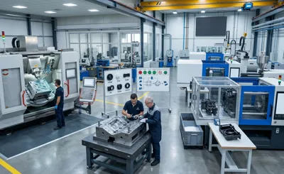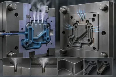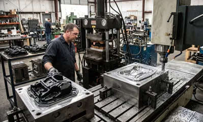
Indentation and deformation in plastic mold design.
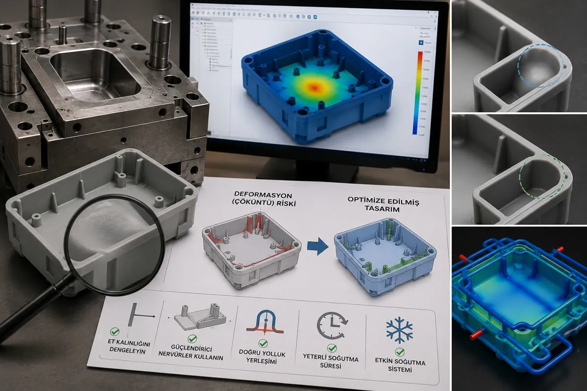
Sink marks and dimensional warpage in plastic mold design result from volumetric shrinkage differences in areas with high wall thickness during the cooling phase of the molten polymer. To prevent these aesthetic and geometric defects, the base wall thickness should be kept homogeneous during the design phase, and the base thickness of the structural support ribs should be dimensioned so that it does not exceed 50% - 60% of the base wall thickness. Positioning the mold cooling channels at equal distances from the male and female cores and optimizing the holding pressure profile with Moldflow thermal simulations guarantees dimensional stability according to ISO 20457 standards.
What Are Sink Marks and Warpage in Plastic Injection Molded Parts?
Among aesthetic plastic housings, automotive interior trim components and household appliance panels supplied to B2B markets, one of the most common defects that reduce product acceptance rates is the formation of sink marks and warpage. A sink mark is a visible surface depression that typically appears directly above a thick section on the opposite side of the part, such as a reinforcing rib, boss or internal support feature.
Warpage, on the other hand, refers to the dimensional distortion that occurs when a molded part loses its intended flatness or geometry after ejection from the mold. Both defects can prevent proper assembly, cause cosmetic quality inspection failures and disrupt B2B manufacturing and supply chains. A professional plastic injection mold design should incorporate the engineering capability to identify and eliminate these potential defects through simulation before any mold steel is machined.
Physical and Thermal Root Causes of Sink Marks
The fundamental cause of sink marks and warpage lies in the thermal behavior of polymers during the molding process. After molten plastic (200°C – 280°C) is injected into the mold cavity, the outer layer that comes into contact with the mold steel cools rapidly and forms a solid skin. However, the inner core of the part, especially in thick-wall sections, cools much more slowly.
As cooling continues, the material in the core undergoes volumetric shrinkage. If the already solidified outer skin is not sufficiently rigid, or if the internal shrinkage forces generated by thick sections are excessive, the surface is pulled inward, resulting in visible sink marks.
Sink Mark Prevention Through Mold Design and DFM Principles
Applying proper Design for Manufacturing (DFM) principles before mold production can eliminate up to 90% of sink mark risks at their source.
1. Uniform Wall Thickness and Core-Out Design
The most important rule in plastic part design is maintaining the most uniform wall thickness possible throughout the component. Sudden wall thickness variations create localized cooling differences that significantly increase the likelihood of sink marks. Thick sections should therefore be reduced using the core-out technique while maintaining mechanical strength through properly designed reinforcing ribs.
2. Rib and Boss Design Ratios
If reinforcing ribs are designed with excessive thickness, they directly create sink marks on the opposite visible surface. To minimize this risk, the rib thickness (Trib) should not exceed approximately 50%–60% of the nominal wall thickness (Twall).
Rib Thickness (Trib) ≤ 0.50 × Twall
The same engineering principle applies to screw bosses. Boss bases should never connect directly to the main wall as a solid mass. Instead, they should be cored out internally and reinforced with thin supporting ribs to reduce localized material accumulation and differential cooling.
3. Gate Location and Thermal Balancing
The gate is the point where molten plastic enters the mold cavity. Ideally, it should be positioned near the thickest section of the component. This allows volumetric shrinkage during cooling to be compensated by additional molten material supplied during the packing (holding) phase. If the gate is located in a thin section, it may freeze before the thicker region has solidified, preventing packing pressure from reaching the critical area and ultimately causing sink marks.
Cooling Channel Design and Its Relationship with Warpage
In addition to sink marks, part distortion or warpage is primarily caused by temperature differences between the core and cavity sides of the mold. For example, if the cavity side operates at 30°C while the core side reaches 60°C, the hotter side experiences greater shrinkage, causing the finished part to bend toward the hotter surface.
To minimize this deformation, cooling channels should follow the three-dimensional geometry of the part wall thickness as closely as possible. Whenever feasible, conformal cooling channels produced by metal additive manufacturing should be employed. The internal mold temperature distribution should ideally remain within approximately ±2°C to ensure uniform cooling throughout the molding cycle.
Preventing Sink Marks Through Process Parameters: The Packing (Holding) Phase
Even with an optimized part and mold design, injection molding process parameters have a significant influence on sink mark formation.
-
Packing Pressure and Holding Time: After the mold cavity has been filled, packing pressure compensates for the volumetric shrinkage that occurs as the polymer cools. Insufficient packing pressure or terminating the holding phase before gate freeze occurs will inevitably lead to chronic sink mark defects.
-
Mold Temperature: Excessively high mold temperatures extend the cooling cycle and increase the likelihood of sink mark formation due to prolonged material shrinkage.
-
Cooling Time: Increasing the cooling time allows the outer skin of the part to fully solidify before ejection, preventing internal shrinkage forces from pulling the surface inward after the part leaves the mold.
Financial Benefits of Sink Mark Analysis in B2B Part Approval Processes
At kaucukplastikkalip.com, we perform advanced Moldflow® simulation analyses before any mold steel is machined. Using sink mark depth analysis, potential cosmetic defects are identified during the design stage rather than after tooling has been manufactured.
Our engineering objective is to maintain calculated sink mark depth below the critical threshold of 0.02 mm. Achieving this target during mold development significantly reduces expensive mold modifications, eliminates steel welding and rework operations, shortens T1 sample approval cycles, and enables us to deliver production-ready parts with outstanding surface quality to our B2B customers on schedule.
Frequently Asked Questions (FAQ)
How Do Sink Marks Appear in Transparent Plastic Parts (PC, PMMA)?
In transparent components, sink marks may appear as visible surface depressions or as internal voids (micro air pockets) located within the wall thickness, creating a lens effect. These defects cause optical distortion and reduce transparency. Proper packing pressure and optimized gate design are essential to prevent such defects.
Are Semi-Crystalline Plastics More Susceptible to Sink Marks?
Yes. Semi-crystalline polymers such as PP, PE, PA6 and POM develop an ordered crystalline structure during cooling, resulting in significantly higher volumetric shrinkage (1.5%–3.0%) than amorphous polymers such as ABS, PC and PS (0.4%–0.7%). Consequently, rib dimensions, wall thickness transitions and cooling design require even greater attention when molding semi-crystalline engineering plastics.
Does Mold Surface Texturing Prevent Sink Marks?
No. Surface texturing (photo-chemical etching) does not physically eliminate sink marks. Instead, it diffuses reflected light, making very shallow sink marks less visible from an aesthetic standpoint. However, deeper sink marks cannot be concealed by texture alone. Proper DFM practices, optimized wall thickness and sound mold engineering remain the only permanent solutions.
Achieve Superior Surface Quality Through Advanced Mold Engineering
Eliminate costly mold modifications, cosmetic defects and production delays before manufacturing begins. At kaucukplastikkalip.com, we combine advanced Moldflow simulation, DFM engineering, optimized cooling channel design and precision injection mold manufacturing to ensure exceptional dimensional stability and surface quality for every project. Share your 3D CAD models, annual production volumes and technical specifications with our engineering team, and receive a customized B2B manufacturing solution designed for maximum production efficiency and long-term reliability.
Recommended for You
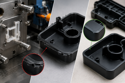
Burr problems in plastic injection molding and solutions.
In plastic injection molding, flash is a dimensional and aesthetic manufacturing defect caused by molten polymer leaking out of mold parting lines, core surfaces, or ejector pin cavities under high injection pressure (>1000 bar). This problem stems from insufficient clamping force, excessive injection speed, mechanical crushing or abrasion of mold kissing surfaces, or polymer melt temperatures that excessively reduce viscosity. Solutions include optimizing compression ratios through Moldflow analysis and revising mold steels with micron-precision laser welding or CNC grinding.