Plastic gear molds
The design of precision plastic gear molds encompasses the production of quiet, high-torque gears used in automotive actuators, medical infusion pumps, and household appliance gearboxes, conforming to AGMA (American Gear Manufacturers Association) and DIN 3967 quality classes (AGMA Q8 - Q11). The non-isotropic shrinkage behavior of semi-crystalline polymers (POM, PA46, PEEK) is balanced by involute profile modification of the mold cavity electrodes and radial shrinkage compensation. The cavities are machined into hardened stainless steel (DIN 1.2083 ESR) using micron-precision Wire EDM and Jig Grinding machines.
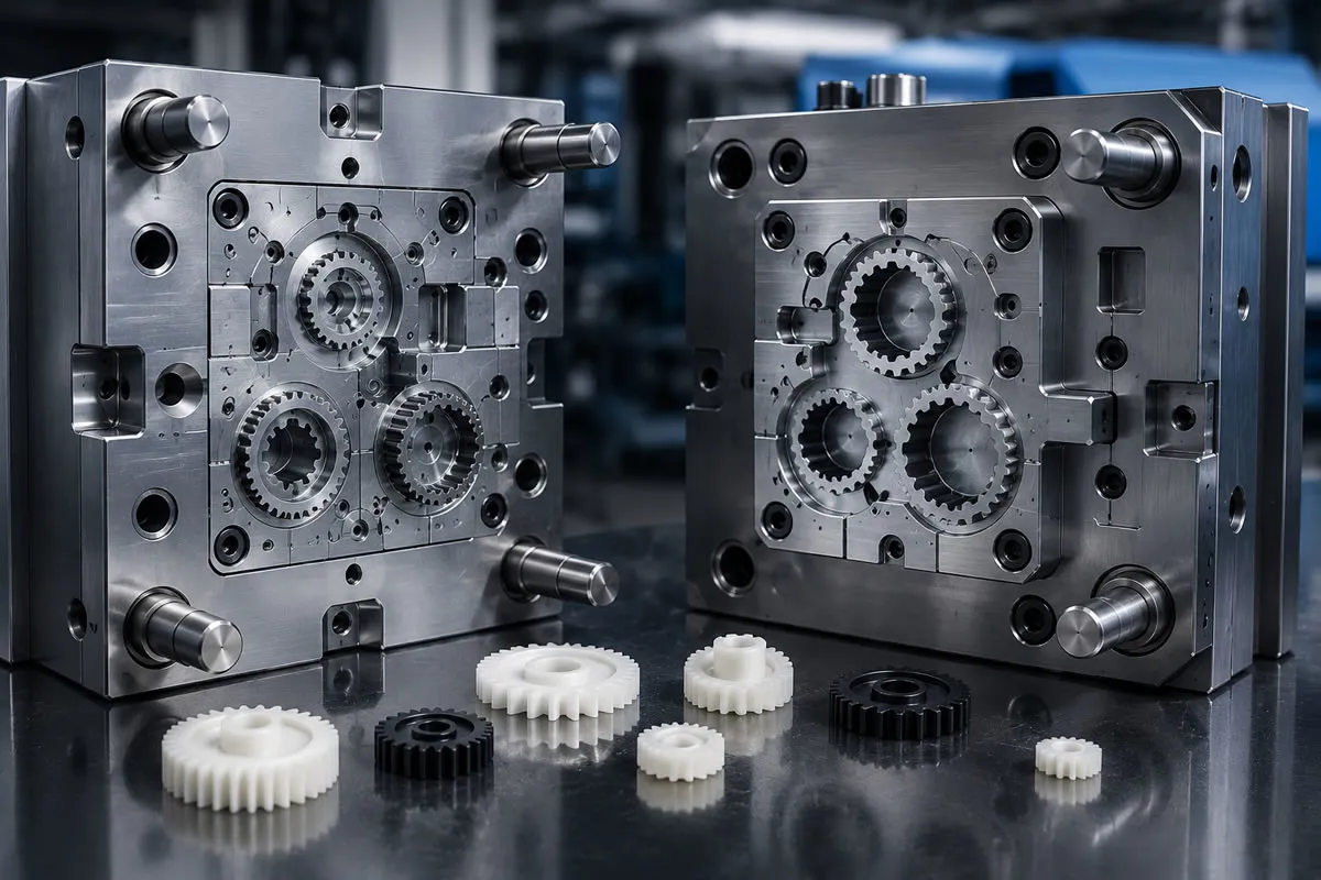
From Metal Gears to Plastic Gears: Quietness, Lightweight Design and Cost Advantage
Traditional steel and brass gears are rapidly being replaced by polymer gears in automotive interior actuators, power window mechanisms, smart home appliances, medical dosing devices, and robotic joint modules. Gears manufactured from engineering plastics provide up to 75% weight savings compared with metals, require no maintenance thanks to their self-lubricating capabilities, and most importantly, provide an ultra-quiet operating environment by damping the resonance and high operating noise (decibel level) generated by metal gears.
However, designing a plastic gear mold is completely different from manufacturing a standard housing or cover mold. Even a 5-micron (0.005 mm) deviation in the involute curve or pitch of a gear can cause the gear to bind, overheat due to high friction, and suffer premature tooth breakage.
Plastic Gear Quality Standards: AGMA and DIN Standards
The dimensional accuracy and tooth profile limits of precision plastic gears are defined by global standards:
AGMA 2000-A88 and ISO/DIN 3967 Quality Classes
According to the standards of the American Gear Manufacturers Association (AGMA), quality grades are classified from Q3 to Q15. As the number increases, gear precision increases:
AGMA Q6 - Q8: Toys, consumer electronics, and simple low-torque mechanisms.
-
AGMA Q9 - Q10 (Precision Class): Automotive actuators, HVAC damper motors, and printer mechanisms. This is the target standard industrial class for injection molding.
-
AGMA Q11 - Q12 (Ultra-Precision): Medical robotic arms, surgical instruments, and aerospace sensor gears. These applications require very tight process control and in-mold pressure sensors.
Total Composite Error (TCE) and Tooth-to-Tooth Error (TTE) Criteria
Two primary error metrics are used in gear quality control:
-
TTE (Tooth-to-Tooth Composite Error): Indicates the angular and form deviation between two adjacent teeth; it directly affects operating quietness.
-
TCE (Total Composite Error): The total eccentricity and tooth-height error over one complete revolution of the gear; it determines whether the gear can rotate without binding.
4 Critical Engineering Rules in Plastic Gear Mold Design
The following engineering methods are applied to achieve the targeted AGMA Q10 class in plastic injection molding:
1. Asymmetric Shrinkage and Involute Profile Modification
Plastic material does not shrink equally in all directions as it cools. Because the tooth tip, base circle, and tooth body have different wall thicknesses, shrinkage is anisotropic. If the standard gear geometry is machined directly into the mold steel, the involute form of the molded gear will emerge flattened and distorted. The mold designer must simulate the shrinkage tensors of the polymer and machine the tooth profile into the steel as an intentionally deformed (modified involute) profile.
2. Diaphragm and Multi-Point Symmetrical Gating Architecture
Maintaining the circular form of spur gears (preventing ovalization) is the greatest challenge. The gate must absolutely not be placed directly on the teeth or on a single side. A gear fed from a single point cools asymmetrically and takes on an egg-shaped form (runout error). The ideal solution is a diaphragm gate feeding through the central shaft hole of the gear or a 3-point / 4-point tunnel gate architecture feeding from the hub at equal angles.
3. Micron-Precision Cavity Manufacturing with Wire EDM
Gear cavities cannot be machined using conventional CNC milling machines. The cavities are cut and transferred into the steel using ultra-precision Wire EDM machines with a positioning accuracy of pm 0.002 mm and 0.10 mm thick brass or molybdenum wires. As the mold steel, 54 HRC DIN 1.2083 ESR stainless steel is used, offering high wear resistance and excellent mirror-polishing capability.
4. Homogenization of Hub, Rim and Ring Wall Thickness
The body section between the gear teeth roots and the central shaft should not be left solid. Solid bodies pull the teeth inward as they cool and distort the gear pitch. A rim-and-spoke architecture should be applied to the gear body, wall thickness should be reduced, and structural strength should be provided using lightly angled webs and ribs.
Material Selection in Gear Manufacturing: POM vs. PA66 vs. PEEK
| Polymer Type | Coefficient of Friction | Wear Resistance | Moisture Sensitivity | Typical AGMA Application |
| POM (Acetal / Delrin) | Very Low ($0.15 - 0.25$) | Excellent | 0.2% (Nearly Zero) | Most common actuator and meter gears |
| PA66 (30% Carbon/Glass Fiber Reinforced) | Medium | Very High | 6.0% (Swells with Moisture) | High-torque gears operating under heavy loads |
| PEEK (Polyetheretherketone) | Low | Extreme | 0.1% (Excellent) | Aerospace and medical gears above +200^C |
Double Flank Gear Measurement Protocols for B2B Suppliers
Gears coming out of the injection line cannot be measured with calipers. At kaucukplastikkalip.com, we test precision gear batches by matching them with master gears on a Double Flank Gear Roll Tester. While the part connected to the master gear is rotated 360^, the spring-loaded measurement probe graphically records axial runout, radial deviation, and composite errors at the micron level. Every shipment batch is delivered with AGMA and DIN quality certification.
Frequently Asked Questions
What is the maximum helix angle that can be used for plastic gears?
In plastic injection molding, helical gears cannot be ejected straight out of the mold; the part must rotate around its own axis while the mold opens and be removed using an unscrewing mechanism. To ensure smooth operation of this unscrewing mechanism, the helix angle is generally kept between 15^ and 30^ at maximum.
Why should POM (Acetal) gears be selected instead of PA66 in humid environments?
Polyamide (PA66) absorbs moisture from the air and expands volumetrically. The expanded gear reduces the center distance, presses against the mating gear, and can cause the mechanism to lock. Since POM does not absorb moisture, it maintains its dimensional form in water or humid climates.
How long is the mold life for plastic gears?
When non-abrasive polymers such as unreinforced POM or PA66 are processed, gear cavities manufactured from 52-54 HRC hardened stainless DIN 1.2083 steel can easily exceed a service life of 1,000,000 (1 million) shots.
Quiet and High-Precision Plastic Gear Solutions to AGMA Standards
Eliminate excessive operating noise, tooth breakage, and axial runout problems in your gears with our advanced mold engineering expertise. At kaucukplastikkalip.com, we manufacture molds with modified involute profiles using our Wire EDM infrastructure and produce quiet plastic gears from POM, PA66, and PEEK materials in accordance with AGMA Q10 standards. Share your 3D CAD models containing your gear module, tooth count, and torque requirements with us and receive your corporate B2B pricing and manufacturing quotation today.
Recommended for You

Smart injection with in-mold pressure sensors.
In-mold pressure and temperature sensors are piezoelectric and infrared (IR) based Industry 4.0 devices that measure the dynamic rheological state of the molten polymer in mold cavities in milliseconds. Instead of relying on the hydraulic pressure of the injection molding machine, these systems read the actual plastic pressure directly within the cavity; they dynamically manage the velocity-to-pressure switchover using the Decoupled III methodology. This technology compensates for inter-batch viscosity fluctuations, preventing flash, short shots, and shrinkage marks at the source, and integrates with part sorting robots to ensure 100% part quality classification.