2K Injection Molding and Design Principles (Two-Component)
Two-component (2K / Two-Color / Multi-Component) injection molding is the process of joining two different polymers (typically a rigid thermoplastic skeleton with a soft TPE/TPU elastomer, or two different colors) at the molecular level in a single cycle using an injection molding machine, rotary table, or transfer robot. Eliminating gluing, screwing, or secondary assembly labor, 2K technology is used in automotive interior trims, power tool housings, and industrial enclosures with integrated sealing gaskets. A successful 2K process depends on the chemical compatibility table based on the surface energies of the polymers, optimized shrinkage compensation, and micron-precise locking systems in male/female cavities.
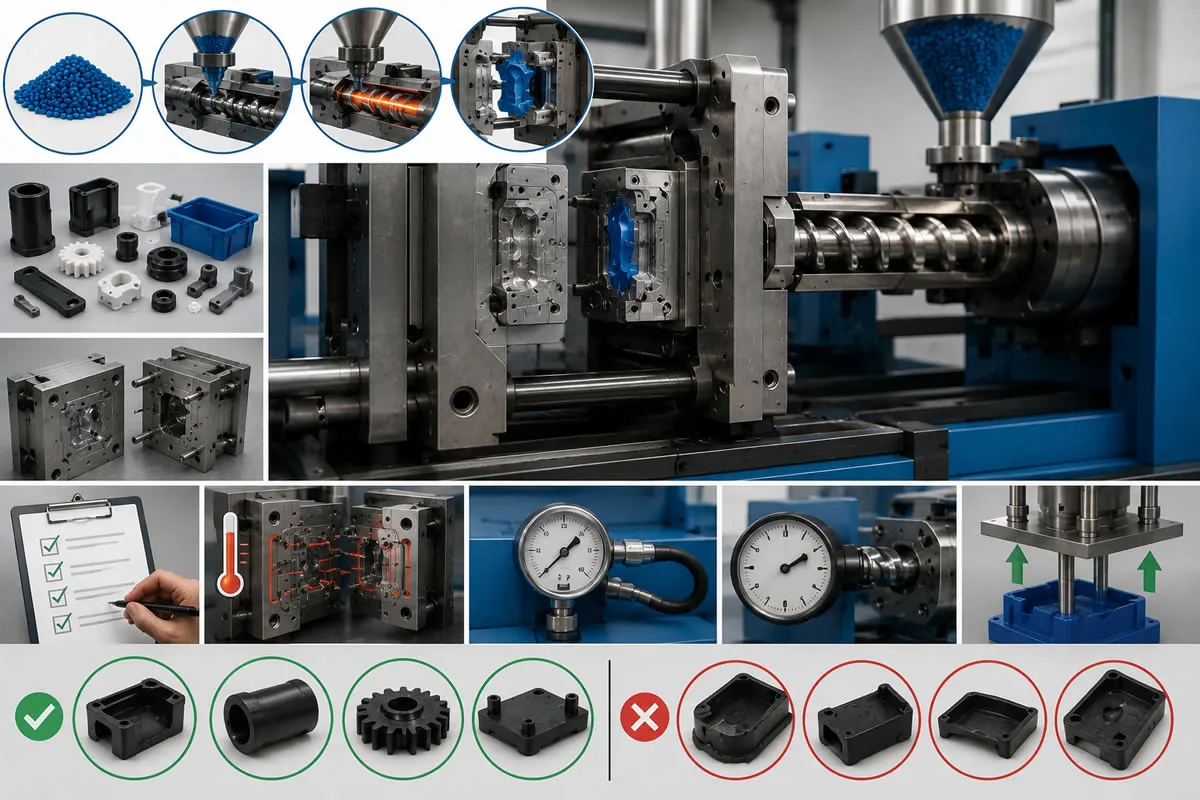
What is 2K Injection Molding? Differences from Conventional Two-Stage Overmolding
As expectations for ergonomics, aesthetics, and functionality in industrial product design increase, single-polymer, monolithic components often fall short. Two-component (2K) injection molding technology comes into play to create non-slip soft-touch surfaces where users interact, integrated sealing gaskets, or dual-color lighting panels.
In conventional manufacturing, the primary rigid component was molded in an injection molding machine, removed and cooled by an operator or robot, and then manually placed into a secondary tool (insert overmolding) to mold the secondary material over it. In 2K technology, these two stages are integrated into a single cycle on the same injection molding machine. The machine features two independent injection barrels (for instance, one horizontal and the other vertical or L-shaped). Because the part bonds with the second material before demolding and without losing its process heat, interfacial adhesion strength reaches maximum levels, completely eliminating operator-induced human errors and secondary assembly lines.
2K Tooling Kinematics and Mechanism Types
The design of 2K molds requires significantly more complex kinematic calculations compared to standard single-shot tooling. The most prevalent mechanism types in the industry include:
1. Rotary Table (180° Rotation) Systems
A hydraulic or servo-driven rotary table is integrated into the moving platen of the injection molding machine. When the mold opens, the rotary table indexes the male core by 180°, aligning the rigid substrate molded at station one directly with the secondary cavities. When the tool closes again, the primary barrel injects the new rigid substrate while the secondary barrel injects the soft elastomer (TPE/TPU) over the rotated component. A finished 2K product is demolded with every cycle.
2. Index Plate and Core-Back Tooling
-
Index Plate: The center block located in the middle of the tool extends axially forward, rotates 180°, and retracts to align the cavities. It serves as an alternative to rotary tables for geometrically asymmetrical components.
-
Core-Back Technology: The mold does not rotate. After the primary material is injected, a hydraulic slide/core inside the cavity retracts with micron-level precision to create a new clearance volume for the second material. The secondary injection unit then shoots TPE into this newly opened volume. Eliminating mold rotation allows operation within more compact mold bases.
3. Robotic Transfer Two-Stage Tooling Cells
For very large parts (e.g., automotive door panels or bumpers) where mold rotation is unfeasible due to clamping tonnage or tie-bar spacing constraints, a 6-axis industrial robot transfers the substrate from the primary cavity to the adjacent secondary cavity within milliseconds.
5 Golden Rules in 2K Part and Mold Design (DFM)
To ensure a zero-defect 2K molding process, the following engineering rules must be observed in part and tool design:
-
Shrinkage Compensation: The volumetric shrinkage rates of the rigid substrate (e.g., PA6 30% GF) and the soft elastomer (e.g., TPE) differ substantially. When machining tool cavities, distinct shrinkage factors must be applied to stage one and stage two to ensure the substrate seats seamlessly into the second cavity upon rotation without binding.
-
Shut-Off and Pinch-Off Land Design: To prevent molten TPE from flashing or weeping across non-targeted surfaces of the substrate during secondary injection, perimeter shut-off steps measuring 0.5 mm to 1.0 mm in width must be engineered directly onto the primary substrate.
-
Mechanical Interlocking: Even when polymers exhibit chemical compatibility, dovetail undercuts, through-holes, or ribs should be designed into the rigid substrate to eliminate peel delamination under severe operational conditions. The overmolded material flows through these openings, locking the geometry mechanically from behind.
-
Gate Location and Thermal Balance: The secondary gate must be positioned strategically to avoid jetting or localized melt-through (thermal degradation/blistering) of thin-walled substrate sections. Valve-gated hot runner systems are typically preferred.
-
Core-to-Core Duplication Tolerance: In rotary table molds, the male core at station 1 and the male core at station 2 must be exact mirror duplicates down to the micron level (±0.005 mm). Any discrepancy will result in cavity tool-steel crashing, pinch misalignment, and flash.
Inter-Polymer Chemical Adhesion Compatibility Matrix
For molecular co-fusion in 2K molding, surface polarity and melting temperature windows must align. Incompatible polymers will not form chemical bonds, resulting in part separation during handling or assembly:
| Rigid Substrate (Component 1) | TPE (Thermoplastic Elastomer) | TPU (Thermoplastic Polyurethane) | Flexible PVC | Liquid Silicone Rubber (LSR) |
| PP (Polypropylene) | Excellent | Poor / None | Poor | Requires Special Primer |
| PA6 / PA66 (Polyamide) | Requires Specially Modified TPE | Excellent | Poor | Excellent (Special Grade) |
| PC / ABS Blend | Good (Modified TPE) | Excellent | Good | Moderate / Good |
| POM (Acetal) | Poor / None | Poor | None | Poor (Mechanical Interlock Required) |
| PBT / PET | Good (Modified TPE) | Excellent | Poor | Good |
Feasibility and ROI Analysis of 2K Tooling Investment for B2B Suppliers
Investing in 2K tooling and multi-component machinery incurs approximately 40% to 60% higher initial capital expenditure (CAPEX) compared to standard single-shot systems. However, high-volume production yields clear economic advantages that accelerate ROI:
-
Secondary Assembly and Bonding Labor: Completely eliminated. The finished multi-material component is ready for end-use directly upon demolding.
-
Quality Control and Scrap Reduction: Human positioning errors, adhesive squeeze-out, adhesive curing delays, and pressure-leak rejects typical of manual secondary bonding are eliminated.
-
Cycle Efficiency: Performing both operations simultaneously within a single machine footprint drastically lowers energy consumption and internal logistics costs per part. For annual production runs of 100,000 units or more, 2K capital investments typically reach amortization within 6 to 10 months.
Frequently Asked Questions (FAQ)
Can a single standard injection molding machine be used for 2K molding?
No. 2K molding requires specialized multi-component injection molding machines equipped with dual barrels (dual hydraulic/electric injection units) and integrated rotary platen control software. However, existing single-barrel machines can be retrofitted for 2K production by mounting an auxiliary bolt-on e-injection unit.
Can TPE be chemically bonded to POM (Acetal)?
POM exhibits an exceptionally inert chemical structure and extremely low surface free energy. There are currently no commercial TPE formulations capable of forming direct covalent bonds with POM. Consequently, when overmolding TPE onto POM, mechanical interlocks, undercut windows, and perforated ribs are mandatory.
How is the hot runner system configured in 2K molds?
Separate, thermally isolated hot runner manifolds are generally utilized for each material. The primary rigid material is typically injected through the stationary machine platen center, while the secondary material is fed via an independent hot runner manifold routed through the top or side of the mold block.
Advanced 2K Tooling Solutions That Eliminate Assembly Costs
Leave behind the operational overhead of producing two separate components and joining them via adhesives or mechanical fasteners. At kaucukplastikkalip.com, we design and build precision rotary table and core-back 2K tooling in-house, scaling rigid-substrate-to-TPE/TPU integration into mass production with micron-level tolerances. Share your 3D CAD data for ergonomic housings, integrated-gasket enclosures, and dual-color components to receive our expert 2K engineering proposal today.
Recommended for You
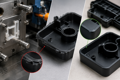
Burr problems in plastic injection molding and solutions.
In plastic injection molding, flash is a dimensional and aesthetic manufacturing defect caused by molten polymer leaking out of mold parting lines, core surfaces, or ejector pin cavities under high injection pressure (>1000 bar). This problem stems from insufficient clamping force, excessive injection speed, mechanical crushing or abrasion of mold kissing surfaces, or polymer melt temperatures that excessively reduce viscosity. Solutions include optimizing compression ratios through Moldflow analysis and revising mold steels with micron-precision laser welding or CNC grinding.