Mold gas release and burn prevention.
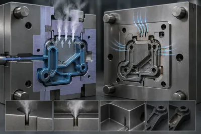
In plastic injection molds, gas venting (ventilation) refers to the design of microchannels that allow the expulsion of ambient air and volatile gases released from the polymer melt during injection. In cases of insufficient gas venting, the trapped gas compresses adiabatically, overheats (>600°C), and creates dieseling/burn marks, leading to black burn marks on the part, short shots, and corrosion of the mold steel. Ventilation depths designed according to polymer viscosity (0.010 mm - 0.040 mm) and sintered porous steel (Porcerax II) inserts reduce the risk of burn marks to zero, increasing cycle speed and weld line strength.
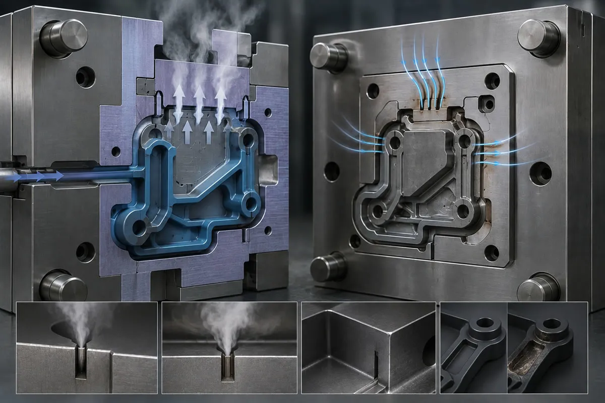
The Physics of Gas Entrapment Inside the Mold: What Is Dieseling?
When a plastic injection mold closes, the cavities are not completely empty; they are filled with air at room temperature. When the injection screw engages, liquid polymer at temperatures between 200^{C} and 300^{C} fills the mold cavities within seconds (or fractions of a second). The rapid entry of the plastic into the cavity causes the existing air inside, along with chemical gases evaporated from the molten plastic (monomers, additives, lubricants), to be swept toward the final point of the flow direction.
If micro-channels through which these trapped gases can escape (mold gas venting / ventilation) have not been designed, the gas becomes trapped in the blind spots of the cavities. The trapped air mass is suddenly compressed adiabatically under the high pressure generated by the melt (1000 - 2000 { bar}). According to the laws of thermodynamics, the temperature of the instantly compressed gas can rise to 600^{C} - 800^{C} within microseconds. Just like the spontaneous ignition of fuel inside the cylinder of a diesel engine, this high temperature burns the plastic and creates a micro-explosion. This phenomenon is known in the plastics industry as the "Dieseling Effect".
Mass Production Defects Caused by Insufficient Gas Venting
Incorrectly designed or clogged venting systems cause three major quality crises in mass production lines:
Surface Discoloration and Burn Marks on the Part (Burn Marks)
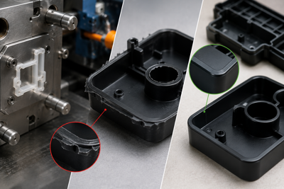
The most obvious indication of dieseling is the presence of carbonized, yellowed, or chemically black burn marks at the blind ends of the flow, at rib tips, or at the bottoms of ribs. These marks create aesthetic defects on the outer surface of the part and directly lead to quality control rejection in white goods, consumer electronics, and automotive components.
Weak Weld Lines and Mechanical Weakness
When two molten plastic flow fronts travel around a hole or core and meet (weld line), the air trapped between them cannot be expelled, preventing the two molten flows from fusing at the molecular level. The micro air pocket remaining between them can cause the part to crack like glass along this weld line during assembly or under load in the field, resulting in structural weakness.
Steel Corrosion and Acidic Discoloration in Cavities
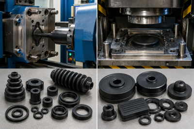
Polymer gases, particularly those generated by PVC, flame-retardant FR materials, and FKM rubbers, contain acidic chemicals. These gases, which cannot be evacuated, adhere to the steel surface and form deposits (plating). Over time, corrosion, rust, and microscopic pits (pitting) develop in the mold cavities, shortening the service life of the mold.
Mold Gas Venting Channel Design Rules
The greatest engineering balance when machining a gas venting channel into a mold is this: the channel must be wide enough for the gas to escape at extremely high speed, yet narrow enough to prevent molten plastic from entering and creating flash. This balance is determined according to the viscosity of the polymer.
1. Ventilation Depth Table by Polymer Type
| Plastic Raw Material Group | Flowability Level | Ideal Ventilation Depth (h) |
| PA6 / PA66 (Polyamide) | Very High (Highly fluid) | 0.010 { mm} - 0.015 { mm} (10 - 15 {m}) |
| POM (Acetal / Delrin) | Very High | 0.012 { mm} - 0.020 { mm} |
| PP / PE (Polypropylene / Polyethylene) | High | 0.015 { mm} - 0.025 { mm} |
| ABS / SAN | Medium | 0.025 { mm} - 0.035 { mm} |
| PC / PMMA (Polycarbonate / Acrylic) | Low (Rigid / Highly viscous) | 0.030 { mm} - 0.045 { mm} |
| PBT (30% Glass Fiber Reinforced) | Medium / High | 0.015 { mm} - 0.025 { mm} |
2. Primary and Secondary Venting Stage Geometry
The gas venting channel is machined into the steel surface in two stages:
-
Primary Stage (Sealing Threshold): Starting from the cavity edge, a channel with a length of 0.8 { mm} - 1.5 { mm} and the micron depth specified in the table above ($0.015 \text{ mm}$) is machined. The plastic cannot pass through this narrow threshold and solidifies.
-
Secondary Stage (Atmospheric Venting Reservoir): From the point where the primary threshold ends to the outer edge of the mold holder, the depth is suddenly increased to 0.5 { mm} - 1.0 { mm}. This wider channel allows the gas to be discharged freely outside the mold without encountering any back pressure.
3. Gas Venting Through Ejector Pins, Cores, and Insert Gaps
Not every vent can be connected to the mold parting line. Moving elements are used for air trapped at the bottom of deep ribs or blind towers of the part:
-
Ejector Pin Clearances: A working clearance of 0.015 { mm} - 0.020 { mm} is maintained between the ejector pin body and its steel housing. Spiral air channels are ground onto the rear shaft of the ejector pin so that the gas can be evacuated through the rear of the pin.
-
Segmented Core Inserts: Instead of machining deep cavities from a single piece of steel, they are manufactured as two-piece structures, with the joints serving as gas venting channels.
Advanced Ventilation Solutions: Porous Steel (Porcerax II) and Vacuum-Assisted Systems
-
Sintered Porous Steel (Porcerax II): This is a patented steel containing approximately 25% microscopic pores (holes with a diameter of 0.02 { mm}) within its metallurgical structure. Inserts made from this steel are installed at the bottoms of ribs where gas entrapment is chronic or at the corners of optical components. While the gas is drawn through the pores of the steel and transferred to the rear venting line, liquid plastic cannot penetrate these pores.
-
Vacuum-Assisted Molding: Before injection begins, the mold perimeter is sealed with O-ring gaskets. As soon as the mold closes, high-speed vacuum pumps remove 99% of the air from the cavity. Plastic injected into an air-free environment encounters virtually no opposing resistance; this technology eliminates dieseling, reduces injection pressure, and accelerates cycle times.
Zero-Burn Assurance and Mold Cleaning Protocols in B2B Part Supply
Even when the gas channels operate perfectly after the mold is commissioned, waxy residues left by gases clog these micro-channels every 20,000 - 50,000 shots during mass production. Clogged channels cause the burn problem to reappear.
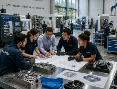
At kaucukplastikkalip.com, we use ultrasonic gas-channel cleaning stations in our mold maintenance plans and maintain open channels during production through air-blown optical inspections. During the DFM stage, we perform Moldflow air entrapment analyses (air trap analysis) and pre-install ventilation channels and sintered air valves at all potential gas entrapment points.
Frequently Asked Questions
How can dieseling burns be distinguished from raw material burning (degradation)?
If the raw material has burned inside the barrel due to excessive temperature or residence time, scattered streaks, silvery swirls, and brown spots appear throughout the part. Dieseling burns, however, appear as localized carbonization only at the corners where the plastic fills last or at the weld lines where two flow fronts meet.
Does reducing the injection speed solve the burn problem?
Reducing the injection speed gives the gas somewhat more time to escape through narrow channels and may temporarily reduce burning. However, this extends the cycle time, creates freeze lines on the part, and is not a structural solution. The permanent solution is to machine gas venting channels into the mold with the correct depth and quantity.
How are gas venting channels cleaned during production?
Without removing the mold from the press, special polymer gas solvent sprays are applied to the parting-line surfaces and wiped with brass or copper spatulas (soft metals that do not scratch the steel). Sandpaper, screwdrivers, or steel wire brushes must never be used; these tools can wear away the micron-depth channels and cause flash.
Burn-Free and High-Strength Plastic Mold Solutions
Permanently eliminate black burn marks, weak weld lines, and gas-related short-shot defects in your parts. At kaucukplastikkalip.com, we design our molds using Moldflow air entrapment analyses and offer zero-burn assurance with polymer-specific, micron-precision two-stage gas venting channels and Porcerax II porous steel solutions. Share your 3D CAD data with us for your mass production projects and receive our expert mold engineering quotation today.
Recommended for You
Automotive rubber and plastic parts manufacturing and OEM solutions.
In the automotive sub-industry, the production of rubber and plastic parts is carried out according to IATF 16949 Quality Management System standards. Active production processes include high-temperature and oil-resistant ACM, AEM, and FKM (Viton) compounds for engine seals, and natural rubber (NR) and EPDM formulations for dynamic damping in suspension lines. Dimensional verifications are performed using 3D CMM devices within the scope of PPAP (Production Part Approval Process) processes and are guaranteed to meet TS ISO 3302-1 M1/M2 accuracy classes.