Smart injection with in-mold pressure sensors.
In-mold pressure and temperature sensors are piezoelectric and infrared (IR) based Industry 4.0 devices that measure the dynamic rheological state of the molten polymer in mold cavities in milliseconds. Instead of relying on the hydraulic pressure of the injection molding machine, these systems read the actual plastic pressure directly within the cavity; they dynamically manage the velocity-to-pressure switchover using the Decoupled III methodology. This technology compensates for inter-batch viscosity fluctuations, preventing flash, short shots, and shrinkage marks at the source, and integrates with part sorting robots to ensure 100% part quality classification.
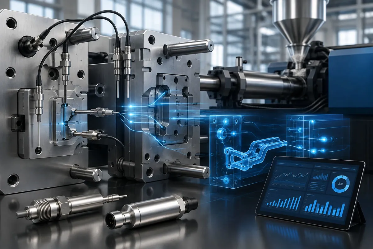
From Machine-Centric Production to Cavity-Centric "Smart Molding"
In conventional plastic injection processes, quality control is generally managed through parameters related to machine hydraulics or screw position. However, micro-fluctuations in barrel temperature, variations in the ratio of recycled regrind material, or changes in ambient humidity and temperature continuously alter the flowability (viscosity) of the polymer. Even if the machine screw advances to exactly the same position during every shot, changes in viscosity can cause the part to be either incompletely filled or over-packed, resulting in flash.
In-mold pressure sensors and temperature sensors move the process away from machine indicators and directly into the cavity where the plastic is located. This approach, known as "Smart Injection Molding", transforms the mold from a passive mass of steel into a source of information that monitors and controls the process with millisecond-level data.
In-Mold Sensor Technologies and Operating Principles
Sensors used in smart molds are miniature components designed to withstand severe pressures inside the cavity (2000 bar) and high thermal shocks:
1. Piezoelectric Pressure Sensors (Direct and Indirect Measurement)
Piezoelectric sensors containing quartz crystals generate an electrical charge (pC - picocoulomb) proportional to the mechanical pressure applied to them. This electrical signal is converted into a pressure curve on digital monitors:
-
Direct Sensors: The front face of the sensor directly faces the mold cavity and comes into contact with the liquid polymer. They provide the most sensitive measurement and are generally used on non-functional or non-cosmetic rear surfaces of the part.
-
Indirect Sensors: These are positioned directly behind an ejector pin. When the molten plastic presses against the ejector pin, the pin compresses the sensor and the pressure is measured indirectly. They leave no visible sensor mark on the part surface.
2. Thermocouples and Fast-Response Infrared (IR) Temperature Sensors
Unlike standard probes that measure the temperature of the mold steel, infrared cavity sensors use sapphire glass optics to measure the core melt temperature of the plastic instantaneously. This data allows the cooling time to be automatically stopped when the part has solidified, optimizing the cycle time on a second-by-second basis.
Scientific Molding (Decoupled III): Sensor-Based V-P Switchover
The most advanced level in scientific injection molding methodology is the Decoupled III process. In this method, the plastic filling phase and the holding/packing phase are completely separated:
-
Phase 1 (High-Speed Filling): Molten plastic is injected at very high speed until it fills 95% - 98% of the cavity volume.
-
Phase 2 (Cavity Pressure-Triggered Switchover): The piezoelectric sensor positioned at the furthest point of the mold detects when the molten plastic reaches that point and the pressure rises to the specified threshold (e.g. 350 bar), and immediately sends a signal to the machine. The machine cuts the filling speed and switches to holding pressure within milliseconds.
-
Phase 3 (Dynamic Holding Pressure Control): Even if the raw material has a more fluid viscosity in that batch, the switchover is based on cavity pressure rather than machine position, making over-packing or flash formation virtually impossible.
4 Key Production Benefits Provided by In-Mold Sensors
| Benefit Area | Conventional Injection Process | Smart Sensor-Based Injection | B2B Production Contribution |
| Raw Material Lot Variations | Manual adjustment by the operator is required | The sensor compensates for viscosity in real time | Zero setup scrap, uninterrupted production |
| Flash and Short Shots | Detected after the part has been molded | Immediately detected when the pressure curve exceeds the limits | 100% consistency in part quality |
| Cycle Time | Cooling time is kept long as a safety margin | The mold opens as soon as the part solidifies | 10% - 20% cycle time savings |
| Mold Protection | Excessive pressure can deform the mold steel | Injection stops when the peak pressure limit is exceeded | Reduced mold maintenance costs |
B2B Supply Assurance: 100% Traceability and Automatic Rejection of Defective Parts
In zero-defect-tolerance industries such as automotive, defense, and medical applications, the fundamental requirement for operating as a B2B supplier is being able to stand behind every part. Pressure-time curves (integral pressure curves) obtained from sensor-equipped molds are recorded on industrial computers.
If the cavity pressure curve in a shot falls outside the target tolerance corridor (for example, if a hot runner nozzle becomes momentarily blocked), the system immediately sends a "REJECT" signal to the part-removal robot. The robot places the part into a locked scrap container rather than on the conveyor belt. This mathematically prevents even a single defective part from reaching the customer's assembly line.
Frequently Asked Questions
Can a pressure sensor be added to an existing mold?
Yes. Existing molds can be taken to the toolroom and integrated by machining pockets for indirect pin-back load cells behind the ejector plate or micro piezoelectric sensors behind a suitable rib. Sensor data can be transferred to external process monitoring displays through a connector connected outside the mold.
Does the sensor leave a visible mark on the part?
Direct cavity sensors may leave a very slight circular sensor contact mark with a diameter of 1 mm - 2.5 mm on the part surface. However, when indirect (behind-the-ejector-pin) sensors are used, the plastic comes into direct contact with the ejector pin, so no additional mark other than the standard ejector mark is created on the part surface.
Is an in-mold sensor investment suitable for small production runs?
For low-volume plastic parts or parts with wide tolerances, it may take a long time to amortize the initial investment cost. However, in medical device components, automotive safety components (airbag connectors, brake valves), and high-cavity (16-32 cavity) packaging molds, the sensor system pays for itself within a few months because it enables scrap-free production.
Smart and Zero-Defect Mold Manufacturing to Industry 4.0 Standards
Permanently eliminate flash, short shots, and dimensional deviations caused by raw material fluctuations in mass production. At kaucukplastikkalip.com, we design piezoelectric pressure and temperature sensor pockets into our mold designs and build smart molds fully compliant with Decoupled III scientific molding principles. Share your 3D CAD models with us for critical projects requiring high precision and 100% quality traceability, and let us provide you with our smart molding B2B quotation.
Recommended for You
Medical LSR (Liquid Silicone) molding technology
In the medical sector, LSR (Liquid Silicone Rubber) molding is an advanced manufacturing method achieved by precisely dosing two-component (A and B) low-viscosity platinum-cured silicone at a 1:1 volumetric ratio, mixing it in a static mixer, and injecting it into hot mold cavities (170°C - 200°C). This process, conducted under ISO 13485 quality management system and ISO Class 7/8 cleanroom infrastructure, ensures full compliance with USP Class VI and ISO 10993 biocompatibility standards, zero flashless precision, and micron-level micro-injection capability. Cold-deck closed valve systems minimize raw material waste.